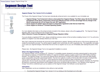
Last week I highlighted an updated tool for designing Foundation fieldbus segments. Emerson’s Jonas Berge left a great comment with links for additional resources to which I wanted to bring visibility in this post. I’ve also inserted some hyperlinks where you can find additional information.
In my personal opinion this software is a great design tool but should be used correctly because the usability of fieldbus has improved also with respect to easier design. Fieldbus has become more powerful and therefore more flexible than it was years ago. Some history: in the early days of fieldbus, the fieldbus power supplies (“conditioners”) had a low output voltage (less than 24 V) and, in particular, intrinsic safety barriers used the ‘entity’ concept which severely limited voltage (11 V) and current (60 mA). Back then fieldbus segments had to be designed one by one, each bus segment calculated to cram in as many devices as the low voltage would permit based on the exact cable length and current draw of each device. Due to the limitations, that design principle was required. Since a large plant has many bus segments, the tool came in very handy to make all these calculations. Because fieldbus power supplies and safety barriers have evolved, that same design principle need not be applied. It is now much simpler.Jonas Berge
Director, Applied TechnologyToday, fieldbus power supplies are much better, providing higher output voltage (32 V) ideal for general purpose, non-incendive, and explosion proof / flame proof installation. For intrinsic safety there is the High Power Trunk (HPT) field barrier concept. With these solutions power is abundant for the devices. This makes it possible to load more devices on each bus, reducing cost. It also makes it easier to design fieldbus, reducing engineering hours, and further reducing cost. There is no longer a need to find out exact cable section lengths or know device current consumption or calculate each bus segment. The projects executing today instead use “typicals” which are worst case boundary condition calculations. For instance, make one calculation to prove that with the selected fieldbus power supply or fieldbus safety barrier it is possible to use 1000 m cable, 12 devices, with an average of 20 mA current draw. Once this is proven, any bus having shorter cable or fewer devices will work. There is no need to redo the calculation over and over for each bus. This means only one or two bus segments are calculated, not hundreds or thousands. This dramatically reduces the amount of engineering hours compared to how fieldbus was engineered for the first projects. There might be a few extreme bus segments for a far away tank farm for which the distance is longer; those few can be calculated individually. Make sure to use the “typicals” design approach for you next project. And make sure to use the SDT to generate and document these ‘typicals’.
The other beauty of using “typicals” is that you can add devices and change the device type without having to recalculate/revalidate the bus segment design as long as you are within the boundary conditions chosen. If you designed for 12 devices, you can easily grow the bus from 8, to 10, to 12 devices. However, if you want to load more devices up to 16 then you have to check again, in which case the SDT [software design tool] software comes in handy again. The beauty of digital communication is that one pair of wires is not limited to one signal, you can connect many devices, each device having many signals. Another advantage of digital communication (and everything digital) is that you can easily make changes, such as adding and changing devices, or adding and changing signals. Using “typicals” makes it easier to take advantage of this digital flexibility to later add more devices on a junction box at will. Unused signals in a device can be incorporated into the control strategy later at a click of a button – doesn’t require hardware. If there are late changes in the project, say the design changes from fieldbus on-off valve to control valve or electric actuator / motor operated valve (MOV) this doesn’t require any fieldbus redesign because as far as fieldbus wiring is concerned they are all the same:
There is no better example than the DeltaV H1 interface card with integral power supplies which over and above this eliminates the need for marshalling cabinets:
Similarly, there is no need to calculate the macrocycle for each bus these days because devices have become so much faster that meeting 250, 500, and 1000 ms requirements is not difficult. Again, you can do a few macrocycle “typicals” for a heavily loaded bus to satisfy yourself that performance will be met. You can easily do this in the DeltaV Control Studio on a laptop; don’t even need a controller connected.
We are teaching “typicals” in the fieldbus workshops we do with customers and EPC that are now using fieldbus technology for the first time.
You can connect and interact with other DeltaV digital bus experts in the DeltaV track of the Emerson Exchange 365 community.


